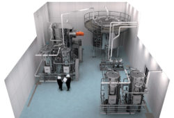
With thousands of water purification machines successfully installed worldwide, MECO serves leading pharmaceutical and biotechnology companies with over 25 million gallons of pharmaceutical grade water each day. The MECO global portfolio includes the broadest range of engineered products for USP Grade Water Treatment, Pure Steam, Purified Water (PW), and Water for Injection (WFI). This depth of global experience ensures we understand the critical nature of maximized up-time for your operations. This is why all of our water purification systems are built around you.
For obvious reasons, the biopharmaceutical industry is one of the most closely regulated, and each component of a pharmaceutical production process must be carefully purified and monitored to prevent the contamination of products. From research and development to the manufacturing of biopharmaceutical products, biopharmaceutical water purification systems play a fundamental role in every stage of biopharmaceutical operations. The different processes in the pharmaceutical industry require different types of water quality, each with its own testing requirements.
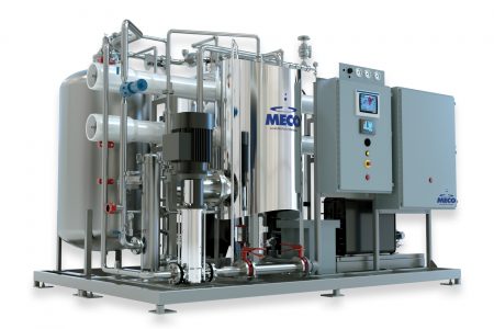
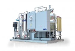
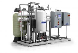
Purified Water (PW) is sufficient for use as a diluent in the production of non-sterile products and for cleaning equipment. Pharmaceutical companies also use purified water as pretreatment in the preparation of Water for Injection (WFI) and pharmaceutical-grade pure steam production.
Some common uses for USP purified water generation systems include:
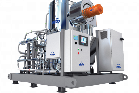
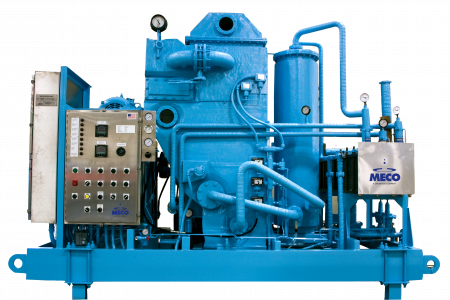
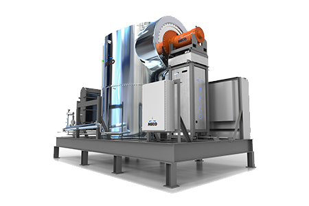
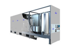
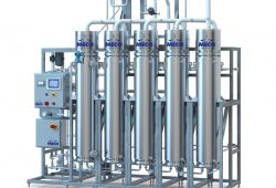
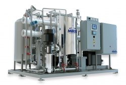
Water for Injection is the more rigorously regulated pharmaceutical water type in the industry. USP Water for Injection is used for diluting substances in the manufacturing of parenteral and ophthalmic products, as well as the final rinsing of packaging. According to certain pharmacopeias, you can produce WFI by multiple effect distillation, vapor compression distillation and membrane-based systems.
Biopharmaceutical manufacturers commonly use WFI in the following applications:
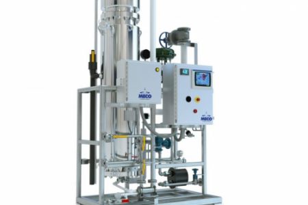
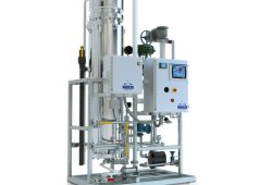
Pharmaceutical-grade pure steam is also referred to as Clean Steam. Both are direct-impact steams produced by a specialized steam generator. When it condenses, it meets the quality characteristics and monographs specified by Pharmacopoeias and regulators for Water for Injection. Pure steam can often be used for the sterilization of pharmaceutical equipment and product sterilization.
Common uses for pure steam in biopharmaceutical applications include:
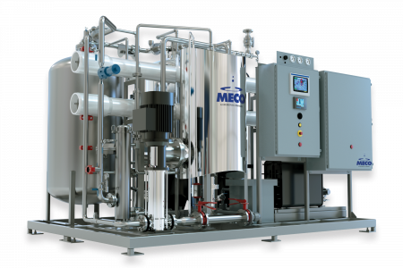
MECO’s Biopharm portfolio includes the broadest range of engineered products for pharmaceutical manufacturing, including Pure Water generation Systems, WFI and Pure Steam. This depth of technology and experience ensures that we understand the critical nature of maximized up-time for your operations.
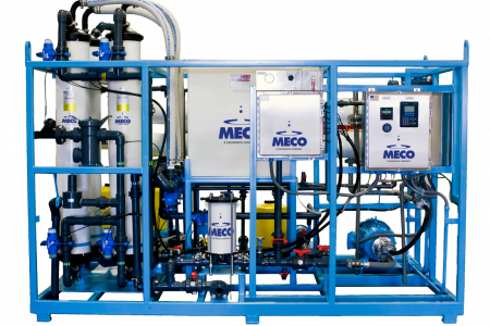
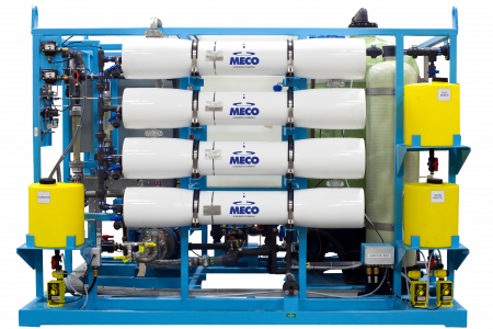
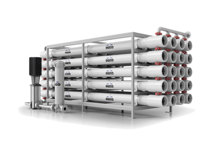
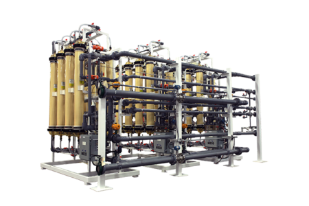
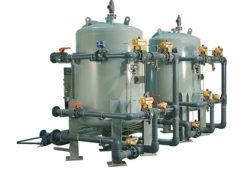
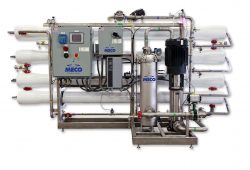
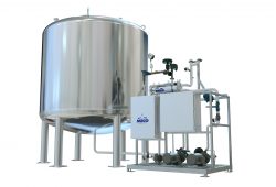
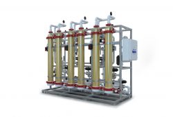
Whatever your pharmaceutical water generation requirements may be, MECO answers with the ideal combination of highly experienced engineers, state-of-the-art manufacturing and first-class service. Discover our broad range of products including Multimedia Filtration, Water Softening, Carbon Filtration, Ultrafiltration, Reverse Osmosis, Multiple Effect Distillation, Vapor Compression Distillation, Membrane-based WFI, and Storage and Distribution. Get in touch today to see how we can help you.

MECO water purification is grounded in our tradition of engineering excellence. Our mastery of core engineering disciplines—mechanical, engineering, drafting—drives a synergy that produces the smartest solution to every challenge.
Productivity is your priority. Maximum uptime is a critical factor. MECO's factory-trained, certified tech team provides services to keep your system running—from onsite water room management to preventive maintenance to emergency response.
MECO technologies are shaping the future of water purification. Our education and training support gives your people the knowledge and confidence to realize all the productivity-enhancing potential we've built into your MECO system.